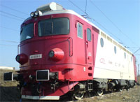
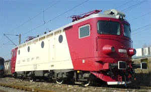
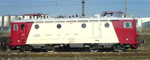
Bo-Bo 3400 kW RetroFit ELECTRIC LOCOMOTIVE WITH THYRISTORS
Upon the request of Romania's National Society of Railway Passenger Transport, "CFR Calatori", we have worked to modernise Bo-Bo 3400 kW electric locomotives. Our goal has been to increase their reliability, enhance compressor and compressed air quality, as well as to improve comfort and working conditions for locomotive drivers. ''
Here are the areas of modernisation we have been focusing on:

- a system of permanent adjustable voltage control on traction motors, with half-controlled bridge rectifier in economic assembly with high energy efficiency
- static voltage and frequency converters for powering the auxiliary services
- integrated information system for monitoring and control of traction and braking
- screw compressor for compressed air production
- joystick for continuously presetting speed and traction current
- effective wheel slip control and protection against axle locking
- modernised driver console
- sliding thermopane glass windows on the sides
- air-conditioning system for the driver cab
- galvanically separated braking resistors
- possibility to separate a traction motor in case of failure
- switched charging station for storage batteries. The amperage supplied to the batteries by the charging station is adjusted depending on voltage and ambient temperature.
- automatic operation mode with preset speed and current parametres
- Modular design
- Benefits:
- increased reliability in operation
- improved operating conditions for traction equipment
- reduced power consumption
- simplified traction and control diagrams
- improved working environment for locomotive drivers
- increased locomotive availability
- longer service intervals
- A system of permanent adjustable voltage control on traction motors. It uses semicontrolled rectifier bridges in economic assembly and has high power parametres. The sequence switch is thus eliminated.
- it ensures lower maintenance costs and a longer lifespan due to the elimination of the sequence switch
- optimisation of traction modes in the sense that the locomotive runs at the constant speed required by the track. This is done through continuous adjustment in the rotative speed of the traction motors, depending on preset speed.
- adjustment of acceleration and deceleration parametres according to the load and a wheel-slip control system
- optimisation of traction equipment functional parametres
- lower power consumption
- operation with a high power factor without harmonic filters
- each traction motor can be isolated in case of failure
- the braking resistor of each traction motor can be completely separated in case of grounding
- increase of traction power due to the adjustment system
- fewer operations by the locomotive driver thanks to the joystick and to the fact that the locomotive runs in an automatic traction mode with preset speed and current parametres.
- Information system based on a microcontroller, which monitors locomotive operation and controls traction and braking modes. It ensures protection, diagnostics, data recording, signalling on colour displays on both dashboard computers, vocal warning of locomotive driver in case of failure. The system can be reset from the dashboard computer.
- it is a flexible system, allowing the connection to other numerical devices already on the locomotive or mounted at a later stage. The recorded information is conveyed to another numerical device for a comparative analysis and storage. This information can also be printed out, serving in statistics for failure categories, operating modes and diagnostics.
- it enables vocal warning: the driver is vocally updated on events related to locomotive operation and the actions he is supposed to undertake. In this way, the system makes the locomotive safer to drive.
- hardware diagnostics can be performed when the system is put into operation
- simplified circuitry, with fewer relays and contactors
- reduced maintenance time
- modular design that follows well-established functions and hierarchies, with many ways of configuration
- operator-friendly display, with a restricted visual field, allowing the driver to monitor and interpret effortlessly and to take adequate action
- graphic display, with automatic and manual adjustment of light intensity, depending on ambient light and the perception of the driver. This leads to a higher level of comfort for the driver.
- The equipment for compressed air production uses a screw compressor driven by a non-synchronous motor with a cage armature and powered from a static voltage and frequency converter. The motor starts by fade up of the voltage and frequency supplied by the static converter:
- increased reliability and efficiency due to the screw compressor
- noiseless operation
- reduced oil quantity in exhaust air and reduced total oil consumption, determining enhanced exhaust air quality
- the air feed is constant in case of big variations of the supply voltage parametre
- the static converter prevents current shocks when the electromotor starts up
- The system of static converters supplying the auxiliary services uses controlled rectifiers with a unitary power factor, as well as synchronised and interdependent control systems:
- the modulating frequency of system rectifiers is multiplied by the number of synchronized converters
- no more "rapping" phenomena in the electric supply network
- electromotors start up without mechanical and current shocks
- the rotative speed of the electromotors is kept constant despite high voltage variation in the catenary aerial cable.
- reduced power consumption, because ventilation power is correlated with traction motor current
 implementing this system on the locomotive requires no changes of roof or floor design for cooling static voltage and frequency converters. Instead, they are cooled by the air inside the locomotive, meaning that the system is highly power efficient.
- we use electromotors of normal coil insulation, because of low converter supply voltage.
- Effective system of wheel slip control and protection against axle locking by means of a sensor with hysteresis, installed in the housing of each reducer. Data concerning axle rotative speed are given by the reluctance variation of the sensor - crown gear assembly.
- optimum use of tractive effort depending on adhesion by means of a control logic which makes it possible to maintain tractive effort at high levels in cases of slippage. Several levels of slippage are used, depending on locomotive speed.
- possibility to identify the motor involved in slippage and to remedy the issue
- for the implementation of rotary transducers no changes need to be made to the axle before it is mounted, so rotary transducers do not limit the number of electric contacts mounted on the axle.
- high reliability because rotary transducers do not have their own moving parts
- outer diameter cutting of railway tyres is needed at longer intervals than before. The system is not affected by the different railway tyre diameters due to automatic calibration.
- data concerning real locomotive speed are highly accurate and not likely to be affected by slippage.
- Air-conditioning system for the driver cab consisting of Coleman air-conditioning equipment; heating by means of PTC heating elements with self temperature limiting characteristics; modernised driver console made of ABS, incorporating equipment manufactured outside Romania; sliding thermopane glass windows on the sides in the driver cab, ergonomic chair, graphic and vocal warning; a system of automatically maintaining preset locomotive speed and preset amperage on traction motors in the traction and braking modes.
- improved comfort for cab driver, making him less subject to stress and fatigue
Modernisation Process: Technical and Functional Solutions
Our modernisation process involves changes in operating modes, circuitry, as well as a rearrangement of locomotive component parts.
To supply traction motors with variable direct voltage, we use series connected and semicontrolled rectifier bridges in economic assembly and with high power parameters. The locomotive is equipped with two semicontrolled rectifiers, each of them supplying a group of traction motors.
A half-controlled RST 2 x 1250/1250 traction rectifier supplies variable direct voltage to a group of traction motors with series field. The group of motors consists of two series connected LJE - 108 motors.
The semicontrolled RST - 2 x 1250/1250 traction rectifier changes the alternative voltage in the secondary traction coils of the main locomotive transformer into adjustable direct voltage by series connection of a semicontrolled double bridge in economic assembly (RTS 2 X 625/1250PDME) with a single semicontrolled bridge (RST 1250/1250 PS), to form a functional equivalent with four voltage levels.
To switch from the traction mode to the electrical braking mode, it is necessary to connect in series the fields of the traction motors and to power them from a single semicontrolled bridge. Each traction motor runs like an alternator with separate excitation and releases power to its own braking resistor.
Semicontrolled rectifiers are built as blocks, having the same size and the same cooling system as the classical high-vacuum rectifier valve.
| No | Technical features | RST 2 x 625/1250 PDME Double bridge |
RST 1250/1250 PS Single bridge |
|---|---|---|---|
| 1. | Rated supply voltage | 2 x 625 VAC | 1250 VAC |
| 2. | Rated frequency | 50 Hz | 50 Hz |
| 3. | Rectified no-load voltage | 0 - 900 VDC | 0 - 900 VDC |
| 4. | Rectified load voltage | 0 - 985 VDC | 0 - 985 VDC |
| 5. | Rectified rated current | 1300 ADC | 1300 ADC |
| 6 | Maximum current for short interval: 5 min | 1715 ADC | 1715 ADC |
The main transformer has been modified so as to allow the supply of the semicontrolled bridges in an economic assembly. We have eliminated the unit comprising the selector and the sequence switch, as well as the switching resistor and its insulators.
The coils of the selves have been connected in series of two and equipped with two-level temperature detectors.
The device units have been modified in such a way as to allow the separation of each traction motor and each braking resistor. In the device units there are current transducers, voltage transducers and supply fuses for the rectifier bridges within the unit.
For supplying the auxiliary services, we use four static voltage and frequency inverters with a unitary power factor, which are mounted on either side of the electrical braking resistor units. They are powered from the socket of the main transformer through the ultra-rapid cut-outs mounted in the high voltage chamber of the main transformer.
The auxiliary services reunite the following power modules:
- screw air compressor 1 x 30kW
- forced ventilation of traction motor 8 x 5, 5kW
- ventilation of braking resistors 4 x 5,5kW
- ventilation of main transformer and of oil pump 1 x 7,5kW + 1 x 1,5kW
The power modules have a redundant supply system, meaning that the inverter working for the braking resistors can replace any inverter from an operational point of view.
The operation of the auxiliary services is controlled and monitored by the information system depending on the state of the voltage protection elements in the catenary hanger and in the circuit breaker, on traction motor medium current etc.
The air source is a screw air compressor of 3,2 m3/min driven by an non-synchronous electromotor with cage armature.
The ventilation system of the traction motors is set depending on their medium current and built on two levels for less noise. The ventilation levels are identified by means of pressure relays, two of them for each unit.
The ventilation systems of the main transformer and of the oil pump are automatically controlled when the circuit-breaker is connected and they run permanently while the locomotive is connected to the catenary hanger.
The control and adjustment electronic equipment is built as a modular unit of removable parts, grouped together according to their main functions (traction, braking, monitoring, diagnostics, slippage, sources etc) and fitted with frontal optical indicators (LEDs ) that indicate state and operating modes.
The control and adjustment electronic equipment enables all the commands needed for the locomotive to run in traction or electrical braking modes. It is adapted to the varying temperature conditions a locomotive can be exposed to and its functions are as follows:
- to switch on the thyristors
- to adjust speed in the automatic mode by means of voltage, current and speed regulators
- to limit traction and braking currents
- protection when prescribed speed or current are exceeded, as well as protection against short circuit and overvoltage
Operationally, the electronic equipment consists of the following units:
The electronic control and adjustment system of the locomotive which adjusts speed in the automatic mode (so that the locomotive is able to run at constant speed equal to prescribed speed and at a prescribed current level) limits maximum current, rotor voltage and field current values. Moreover, the system makes it possible to select working mode and monitors the execution of the control diagram by contactors and reversers according to the position of the controller and to the assigned working mode.
The electronic system for signalling, data recording and diagnostics monitors the traction-braking modes, the operation of the auxiliary services, the protection systems, the state of various devices in the circuitry of the locomotive (insulation switches, relays, contactors, push-in fuses, electromagnetic circuit-breakers), the voltage and current values of each traction motor, traction motor rotative speed and the electrical values of the auxiliary services. The system adjusts the rectifying bridges by means of optical fiber according to prescribed current and speed values. It also controls the heating of the main transformer and of the flattening self, the ventilation equipment and the differences in the rotative speeds of the axles. This is needed to reduce, block or increase voltage in the traction motor with varaible slopes, depending on the operating modes of the locomotive. The system is based on a microcontroller and a recorded software logic.
The electronic system for signalling, data recording and diagnostics receives digital and analogical data which define the operational mode of the locomotive. It processes these data and serially conveys them to the displaying units of the two dashboard computers. These units have colour displays of adjustable brightness and vocal modules.
By downloading data with the aid of a high-speed USB port and an application for interpreting recorded data, we can get charts of all the values monitored by the system before an event occurs and we can draw up statistics for failure categories, graphs etc.
The wheel slip and axle locking control system processes the signals sent by the rotary transducers installed upon each reducer and commands a certain voltage reduction or limitation on the motor group of the slipping axle, depending on locomotive speed, slippage degree etc. When an axle is locked, it commands the disengagement of the bogie with the blocked axle and rapidly reduces the electric braking force of the locomotive.
Maintenance and Repairs
The main equipment we modernise incorporates electronic elements with static commutation that do not require maintenance.The products are easily repaired due to their modular design, meaning that downtime is shorter in case of failure.
In terms of locomotive maintenance and overhaul, our modernisation activities lead to significantly less time needed for troubleshooting and repair, owing to real-time failure reporting on the displays in the driver console.
Railway operators that use thyristorised locomotives similar to the one made by PROMAT and LJE 108 engines have experienced longer overhaul cycles, extending to 92 days with 8-hour downtime (also known as technical revisions). Ultrasonic control and changes of traction motor brushes need to be done every year.
Features of the Rail Track and Operating Conditions
- Gauge - according to STAS 4397 - 75 standard: 1435 mm
- Minimum radius in bends:
- in the locomotive shed: 90 m
- at the railway switch: 170 m
- in running line: 250 m
- Maximum value of the aggradations: 150 mm
Constructive and Functional Features
- Type EC / EC1
- Axle formula: Bo-Bo
- Length over buffers: 15890 mm
- Width of the box: 3100mm
- Gap between the upper side of the rail end and the upper edge of the pantograph when lowered: 4650mm
- Diameter of new wheel: 1250mm
- Diameter of half-worn wheel: 1210mm
- Total weight:
- with electrical brake 80 MT
- without electrical brake 78 MT
- Axle load:
- with electrical brake 21 MT
- without electrical brake 20 MT
- Rated output according to UIC (International Union of Railways): 3400kW
- Traction force
- per hour: 19,2 tf for EC and 14,3 tf for EC1
- for longer intervals: 17,9 tf for EC and 13,3 tf for EC1
- Gear ratio: 73/20 for EC and 104/38 for EC
- Main transformer: modified MLR 5500
- LJE108 traction motors with series field
- Number of steps of field weakening: 3
- Braking resistance of friction: 0,42 ohm